New DLP Design Product Announcements:
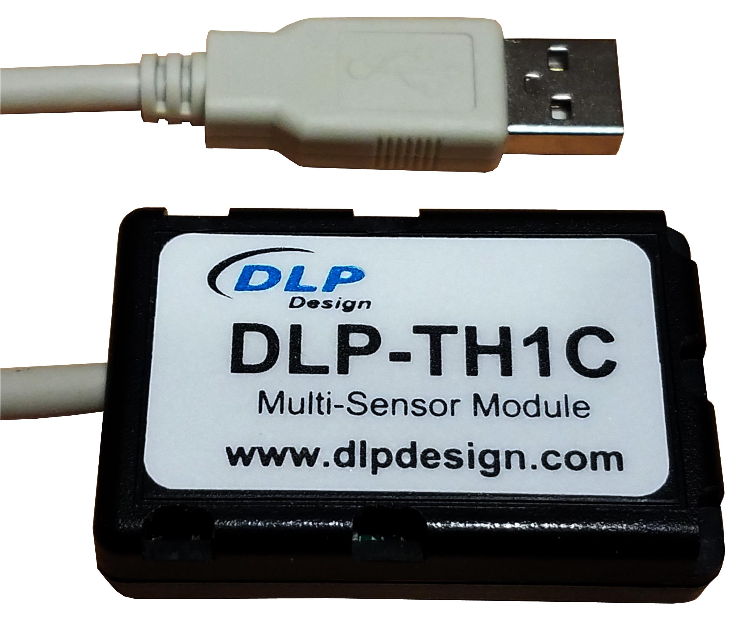
DLP-TH1C Multi-Sensor Module
DLP Design, Inc. is pleased to announce the new DLP-TH1C.
The DLP-TH1C is a USB-based module for acquiring temperature, humidity, pressure, sound, tilt,
vibration and light data. A rudimentary host app and its source-code project (Visual Studio,
Visual C++) is provided with the DLP-TH1C to demonstrate host communication via Virtual COM
Port (VCP). All features of the DLP-TH1C can be accessed via single-byte commands from the
host application.
Download the DLP-TH1C datasheet for more details.
|
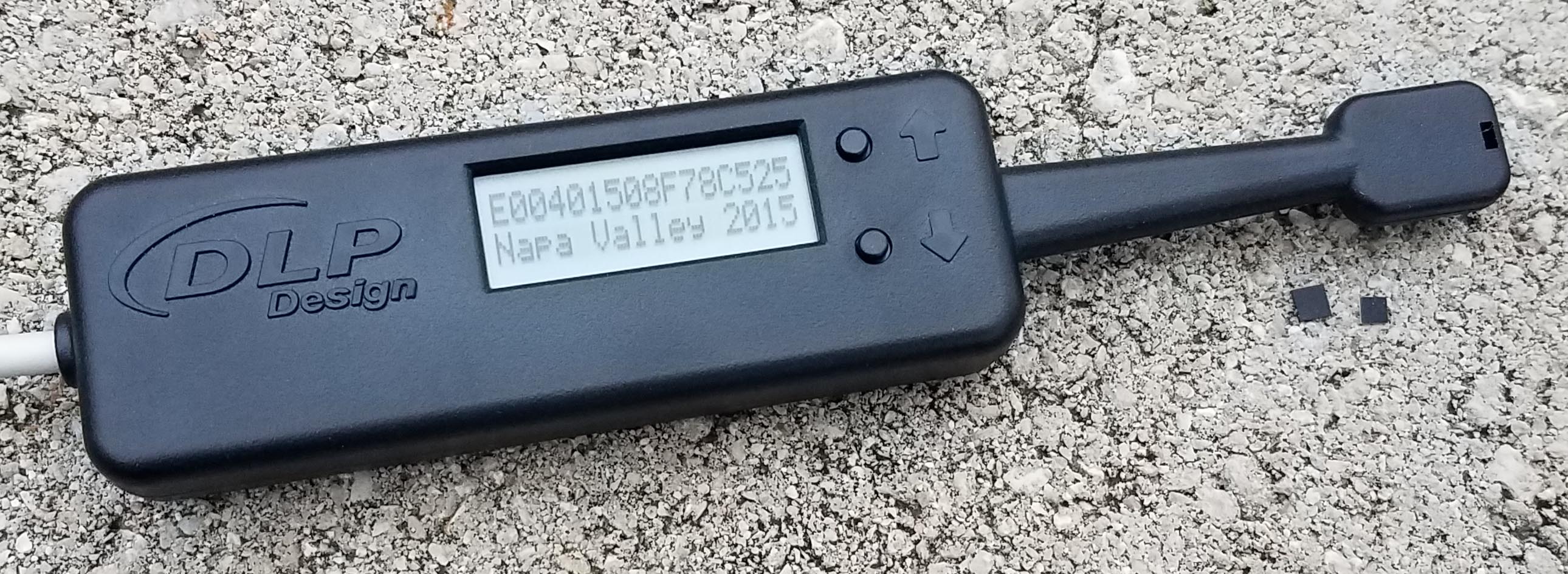
DLP-RFID2P 13.56MHz Reader/Writer
DLP Design, Inc. is pleased to announce the new DLP-RFID2P
HF RFID reader/writer.
The DLP-RFID2P is based on our popular DLP-RFID2 module. At power up, this device will
read both the UID and stored user memory from ISO15693 tags and present this data on the backlit LCD display while in
Local Mode. Up and Down buttons allow for scrolling through the user data on the LCD display. It can be powered from
either a host PC or USB battery pack. A host PC is required in order to write to ISO15693
tags via the USB interface using the provided Windows app. Both Virtual COM Port drivers and Keyboard Emulator methods
of host PC interface are available for the Remote Mode interface.
Download the DLP-RFID2P datasheet for more details.
Watch our 3-minute introductory video below:
|
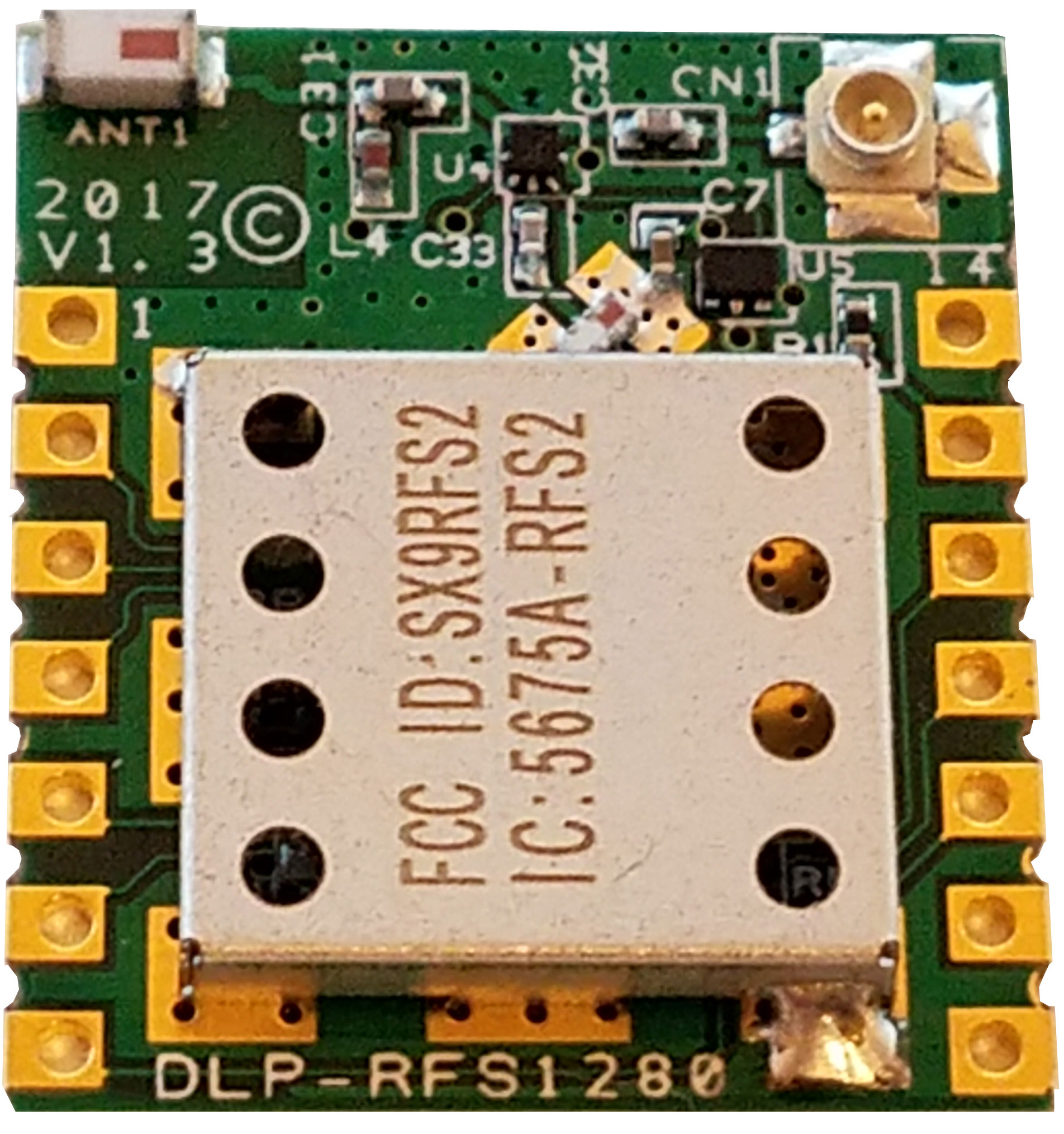
DLP-RFS1280 2.4GHz LORA RF Transceiver Module with Modular Certification
December 2017 (Updated May 2018): DLP Design, Inc. is pleased to announce the DLP-RFS1280
pre-certified module based on the SX1280 transceiver chip from Semtech Corporation. This new module
implements the Semtech SX1280 transceiver, and is designed to work with an external, user-supplied
microcontroller.
The feature set for this module includes:
FCC / IC / RED / MIC Modular Certifications in Place
On-Board Chip Antenna
U.FL Connector for External, User-Supplied Antenna
+11.5dBm Transmit Power
-131dBm Receive Sensitivity
<5.5mA Receive Current
Surface or Through-Hole Mount, 2x2.3cm Footprint
Also announced today, the DLP-RFS1280ACT demonstration platform has the following features:
Simple Pairing Method with Other Transceiver
Fully-Commented Demonstration C Source Code
Low-Power NUCLEO-L073RZT6 Microcontroller Development Board
Ranging (Distance-Measurement) Demonstration in Meters/Feet
Lighted LCD Display
Speaker/Microphone for Walkie-Talkie (Push-To-Talk) Demonstration
Whip Antenna
Internal/External Antenna Selection
Easy Mode Selection (LORA/FLRC/GFSK)
Long-Range Ping Test
CW and Modulated CW Settings
Internal/External Antenna Selection during Demonstrations
Running on the STMicroelectronics STM32L073RZ microcontroller, this demonstration platform
requires less than 55K of FLASH program memory to perform all of its functions.
Download the DLP-RFS1280 datasheet.
Just Announced: The DLP-RFS-LOCATOR demonstrates an implementation of the DLP-RFS1280 module whereby
lost items can be found using both the Ranging (distance-measurement) feature of the SX1280 as well as a high-gain
Yagi antenna for determining the direction to the lost item. For this demonstration, the
DLP-RFS1280ACT serves as the "lost item", and its location (both distance and direction) is determined by the
DLP-RFS-LOCATOR wand.
DLP-RFS1280
|
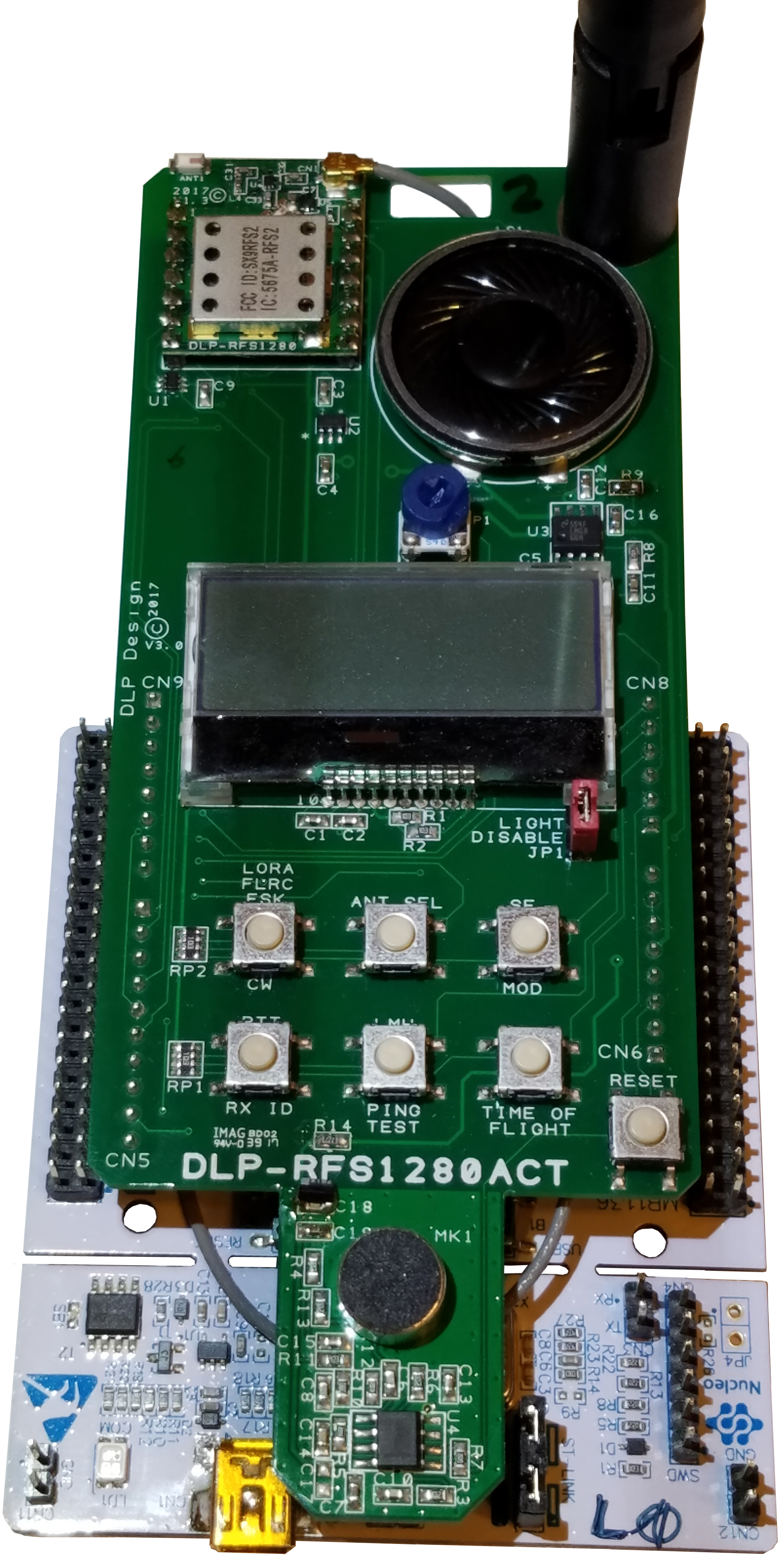
DLP-RFS1280ACT*
|
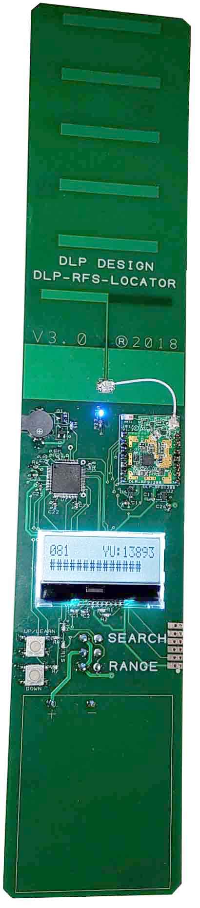
DLP-RFS-LOCATOR*
More Info
|
The DLP-RFS1280 is available from
our distribution network.
|
The DLP-RFS1280ACT is available from
our distribution network.
|
The DLP-RFS-LOCATOR is available from
our distribution network.
|
*Note: In order to properly demonstrate these transceiver products, it is required to have a minimum of two
transceivers: Two (2) DLP-RFS-1280ACT, or both a DLP-RFS-LOCATOR and a DLP-RFS1280ACT.
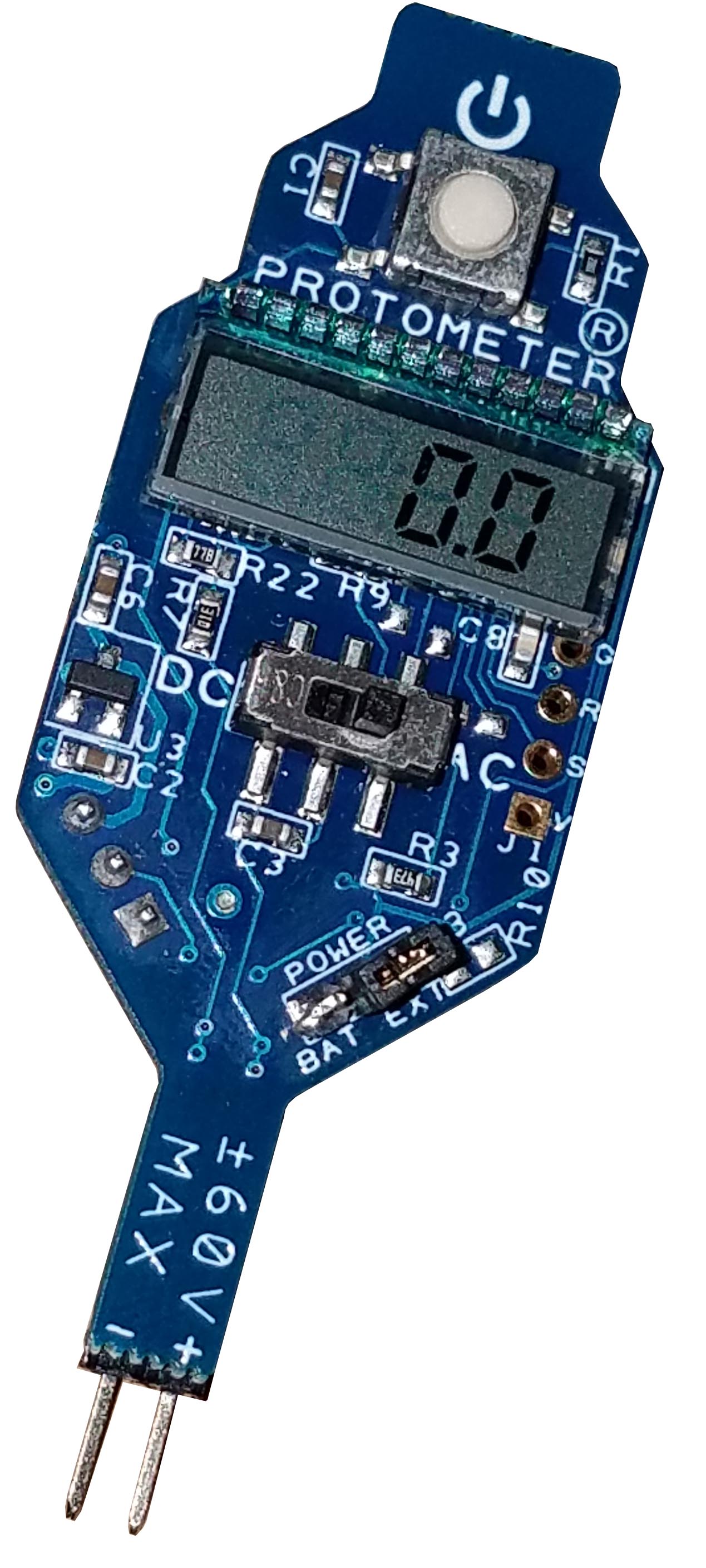
DLP-PMV Hands-Free Voltmeter
DLP Design, Inc. is pleased to announce the new PROTOMETER® voltmeter.
The PROTOMETER (Part Number: DLP-PMV) frees your hands and helps control clutter on your workbench as you test and modify
the circuitry on your breadboard. No more having to hold voltmeter test leads to monitor DC or AC (RMS) voltages - simply
plug a PROTOMETER into your breadboard and turn it on. Voltages up to 60V are displayed on the
miniature LCD display. The PROTOMETER is powered by a single coin cell, and it is small enough to accommodate multiple meters
monitoring multiple voltages on even a small breadboard.
Download the DLP-PMV owner's manual for more details.
|
 |
CDM Uninstaller: Program for selectively
removing FTDI devices with specific VID and PID combinations. Read the
manual for more details.
MPROG: EEPROM mode-configuration program V3.5 (This is a
legacy utility and has been replaced by FT_Prog. MPROG supports the FT2xxBM/L, FT2xxR and FTDI's high-speed ICs.)
MPROG V3.5 User's Guide
FT_Prog: EEPROM programming utility for use with
FTDI devices. It is used to customize the EEPROM contents and can modify information such as device descriptors.
USBView Program: View the VID and PID of all connected USB
devices even without drivers loaded.
Current Versions of FTDI Drivers:
CDM (Combined Driver Model Version 2.12.28) Windows Drivers:
WHQL-certified USB drivers -- required for 64-bit Windows systems.
FTDI default VID/PID values (0403/6001 for single channel, 6010 and 6011 for dual) listed
in the .inf files must be programmed into EEPROM using MPROG or FT_PROG.
 You can either download the WHQL certified driver files above or use the install executable to install them.
- Make sure the USB device is not plugged in.
- Download the FTDI driver install executable.
- Run the driver exe file.
- Wait for the command window to vanish.
- Plug in the USB device and the driver will load.
CDM (Combined Driver Model Version 2.8.14) Windows Drivers:
Modified .inf files for use with specific DLP Design products on XP/Vista/Windows 7 systems (DLP-TH1b, DLP-TILT, DLP-D-G, DLP-RFID1, DLP-UT1, DLP-UTH8).
See Note 1
Note 1: In order to use the listed DLP Design products on a 64-bit machine, the VID/PID
values in the EEPROM area must first be changed to the FTDI default of 0403/6001 (0403/6010 and 0403/6011 for dual-channel products) so that
the WHQL-certified drivers will load. Use the MPROG utility (above) on a non-64 bit (ex: XP) machine to update the values
in the EEPROM. You can also hold down F8 during boot on a 64-bit PC and disable the driver certification check so that the non-certified
drivers can be loaded and the PID changed using MPROG.
For more info: TN_129
Note 2: If an extra COM port is not available after installing the latest CDM driver, connect the USB device and open
Control Panel > System > Device Manager. Right click on USB Serial Converter under USB Controllers and select Properties, then
the Advanced tab. Check the box marked "Load VCP", then click OK. Unplug and re-plug the USB device, and the COM port will be
added. This method is also used to change the driver mode from VCP to D2XX (DLL).
More FTDI Drivers
FTDI App Notes
|
|